Downhole Chemical Injection Lines-Why Do They Fail? Experiences, Challenges and Application of New Test Methods
Copyright 2012, Society of Petroleum Engineers
Abstract
Statoil is operating several fields where downhole continuous injection of scale inhibitor is applied. The objective is to protect the upper tubing and safety valve from(Ba/Sr) SO4orCaCO; scale, in cases where scale squeezing maybe difficult and costly to perform on a regular basis, e.g. tie-in of subsea fields.
Continuous injection of scale inhibitor downhole is a technically appropriate solution to protect the upper tubing and safety valve in wells that have scaling potential above the production packer; especially in wells that do not need to be squeezed on a regular basis due to scaling potential in the near wellbore area.
Designing, operating and maintaining the chemical injection lines demand extra focus on material selection, chemical qualification and monitoring. Pressure, temperature, flow-regimes and geometry of the system may introduce challenges to safe operation. Challenges have been identified in several kilometers' long injection lines from the production facility to the subsea template and in the injection valves down in the wells.
Field experiences showing the complexity of downhole continuous injection systems regarding precipitation and corrosion issues are discussed. Laboratory studies and application of new methods for chemical qualification a represented. The needs for multidisciplinary actions are addressed.
Introduction
Statoil is operating several fields where downhole continuous injection of chemicals has been applied. This mainly involves injection of scale inhibitor(SI) where the objective is to protect the upper tubing and downhole safety valve(DHSV) from (Ba/Sr) SO4orCaCO; scale. In some cases emulsion breaker is injected downhole to start the separation process as deep in the well as possible at a relative high temperature.
Continuous injection of scale inhibitor downhole is a technically appropriate solution to protect the upper part of the wells that have scaling potential above the production packer. Continuous injection might be recommended especially in wells that do not need to be squeezed because of low scaling potential in the near wellbore; or in cases where scale squeezing maybe difficult and costly to perform on a regular basis, e.g. tie-in of subsea fields.
Statoil has extended experience on continuous chemical injection to topside systems and subsea templates but the new challenge is to take the injection point further deep into the well. Designing, operating and maintaining the chemical injection lines demands extra focus on several topics; such as material selection, chemical qualification and monitoring. Pressure, temperature, flow-regimes and geometry of the system may introduce challenges to safe operation. Challenges in long (several kilometers) injection lines from the production facility to the subsea template and into the injection valves down in the wells have been identified; Fig.1. Some of the injection systems have worked according to plan, while others have failed for various reasons. Several new field developments are planned for downhole chemical injection (DHCI); however; in some cases the equipment has not been fully qualified yet.
Application of DHCI is a complex task. It involves the completion and well designs, well chemistry, topside system and the chemical dosage system of the topside process. The chemical will be pumped from topside via the chemical injection line to the completion equipment and down into the well. Hence, in the planning and execution of this type of project cooperation between several disciplines is crucial. Various considerations have to be evaluated and good communication during the design is important. Process engineers, subsea engineers and completion engineers are involved, dealing with the topics of well chemistry, material selection, flow assurance and production chemical management. The challenges can be chemical gun king or temperature stability, corrosion and in some cases a vacuum effect due to local pressure and flow effects in the chemical injection line. In addition to these, conditions such as high pressure, high temperature, high gas rate, high scaling potential,long distance umbilical and deep injection point in the well, give different technical challenges and requirements to the chemical injected and to the injection valve.
An overview of the DHCI systems installed in Statoil operations shows that the experience has not always been successful Table 1. However, planning for improvement of the injection design, chemical qualification, operation and maintenance is being undertaken. The challenges vary from field to field, and the problem is not necessarily that the chemical injection valve itself is not working.
Over the last years several challenges concerning downhole chemical injection lines have been experienced. In this paper some examples are given from these experiences. The paper discusses challenges and measures taken to solve the problems related to DHCI lines. Two case histories are given; one on corrosion and one on chemical gun king. Field experiences showing the complexity of downhole continuous injection systems regarding precipitation and corrosion issues are discussed.
Laboratory studies and application of new methods for chemical qualification are also considered; how to pump the chemical, scaling potential and prevention, complex equipment application and how the chemical will the affect the topside system when the chemical is produced back. Accept criteria's for chemical application involves environmental issues, efficiency, storage capacity topside, pump rate, whether existing pump can be used etc. Technical recommendations must be based upon fluid and chemistry compatibility, residual detection, material compatibility, subsea umbilical design, chemical dosage system and materials in the surroundings of these lines. The chemical might need to be hydrate inhibited to prevent plugging of the injection line from gas invasion and the chemical must not freeze during transport and storage. In the existing internal guidelines there is a checklist of which chemicals can be applied at each point in the system Physical properties such as viscosity are important. The injection system may imply 3-50km distance of umbilical subsea flow line and 1-3km down into the well. Hence, the temperature stability is also important. Evaluation of downstream effects, e.g. in refineries may also have to be considered.
Downhole chemical injection systems
Cost benefit
Continuous injection of scale inhibitor downhole to protect the DHS Vor the production tubing maybe cost effective compared to squeezing the well with scale inhibitor. This application reduces the potential for formation damage compared to scale squeeze treatments, reduces the potential for process problems after a scale squeezes and gives a possibility to control the chemical injection rate from the topside injection system. The injection system may also be used to inject other chemicals continuously downhole and can thereby reduce other challenges that might occur further downstream the process plant.
A comprehensive study has been performed developing a downhole scale strategy of the Oseberg S or field. The major scale concern was CaCO; scaling in the upper tubing and possible DHSV failure. The Oseberg S or scale management strategy considerations concluded that over a three year's period, DHCI was the most cost efficient solution in the wells where the chemical injection lines were functioning. The main cost element with regards to the competing technique of scale squeeze was the deferred oil rather than the chemical/operational cost. For application of scale inhibitor in gas lift, the major factor on the chemical cost was the high gas lift rate leading to high S I concentration, since the concentration had to be balanced with the gas lift rate to avoid chemical gun king. For the two wells on Oseberg S or that had well-functioning DHC I lines, this option was chosen to protect the DHS V's against CaCO; scaling.
Continuous injection system and valves
Existing completion solutions using continuous chemical injection systems face challenges to prevent plugging of the capillary lines. Typically the injection system consists of a capillary line, 1/4” or 3/8” outside diameter (OD), hooked up to a surface manifold, fed through-and connected to the tubing hanger on the annular side of the tubing. The capillary line is attached to the outer diameter of the production tubing by special tubing collar clamps and runs on the outside of the tubing all the way down to the chemical injection mandrel. The mandrel is traditionally placed up-stream of the DHS V or deeper in the well with the intention of giving the injected chemical sufficient dispersion time and to place the chemical where the challenges are found.
At the chemical injection valve, Fig.2, a small cartridge about 1.5” in diameter contains the check valves which prevent wellbore fluids from entering the capillary line. It is simply a small poppet riding on a spring. The spring force sets and predicts the pressure required to open the poppet off the sealing seat. When the chemical starts flowing, the poppet is lifted off its seat and opens the check valve.
It is required to have two check valves installed. One valve is the primary barrier preventing the wellbore fluids from entering the capillary line. This has a relatively low opening pressure (2-15bars) .If the hydrostatic pressure inside the capillary line is less than the wellbore pressure, the wellbore fluids will try to enter into the capillary line. The other check valve has atypical opening pressure of 130-250 bars and is known as the U-tube prevention system. This valve prevents the chemical inside the capillary line to freely flow into the wellbore should the hydrostatic pressure inside the capillary line be greater than the wellbore pressure at the chemical injection point inside the production tubing.
In addition to the two check valves, there is normally an in-line filter, the purpose of this is to ensure that no debris of any kind could jeopardise the sealing capabilities of the check valve systems.
The sizes of the described check valves are rather small, and cleanliness of the injected fluid is essential for their operational functionality. It is believed that debris in the system can be flushed away by increasing the flowrate inside the capillary line, so that the check valves willfully open.
When the check valve opens, the flowing pressure rapidly decreases and propagates up the capillary line until the pressure again increases. The check valve will then close until the flow of chemicals builds up sufficient pressure to open the valve; the result is pressure oscillations in the check valve system. The higher opening pressure the check valve system has, the less flow area is established when the check valve opens and the system tries to achieve equilibrium conditions.
The chemical injection valves have a relatively low opening pressure; and should the tubing pressure at the chemical inlet point become less than the sum of hydrostatic pressure of chemicals inside the capillary line plus the check valve opening pressure, near vacuum or vacuum will occur in the upper part of the capillary line. When the injection of chemical stops or the flow of chemical is low, near vacuum conditions will start to occur in the top section of the capillary line.
The level of vacuum is dependent on the wellbore pressure, specific gravity of the injected chemical mixture used inside the capillary line, the check valve opening pressure at the injection point and the flowrate of the chemical inside the capillary line. The well conditions will vary over the field lifetime and the potential for vacuum will therefore also vary overtime. It is important to be aware of this situation to take the right consideration and precaution before expected challenges occur.
Together with low injections rates, typically the solvents used in these types of applications are evaporating causing effects that have not been fully explored. These effects are gun king or precipitation of solids, for example polymers, when the solvent is evaporating.
Further, galvanic cells can be formed in the transition phase between the fluid surface of the chemical and the vapour filled near-vacuum gas phase above. This can lead to local pitting corrosion inside the capillary line as a result of increased aggressiveness of the chemical under these conditions. Flakes or salt crystals formed as a film inside the capillary line as its interior dries out could jam or plug the capillary line.
Well barrier philosophy
When designing robust well solutions, Statoil requires that the well safety is in place at all times during the lifecycle of the well. Thus, Statoil requires that there are two independent well barriers intact. Fig. 3 shows atypical well barrier schematic, where the blue color represents the primary well barrier envelope; in this case the production tubing. The red color represents the secondary barrier envelope; the casing. On the lefthand side in the sketch the chemical injection is indicated as a blackline with injection point to the production tubing in the area marked red (secondary barrier). By introducing chemical injection systems into the well, both the primary and secondary wellbore barriers are jeopardized.
Case history on corrosion
Sequence of the events
Downhole chemical injection of scale inhibitor has been applied into an oilfield operated by Statoil on the Norwegian Continental Shelf. In this case the scale inhibitor applied had originally been qualified for topside and subsea application. Recompletion of the well was followed by installation of DHCIpointat2446mMD, Fig.3. The downhole injection of the topside scale inhibitor was started without further testing of the chemical.
After one year of operation leakages in the chemical injection system were observed and investigations started. The leakage had a detrimental effect on the well barriers. Similar events occurred for several wells and some of them had to be shut-in while the investigation was ongoing.
The production tubing was pulled and studied in detail. The corrosion attack was limited to one side of the tubing, and some tubing joints were so corroded that there was actually holes through them. Approximately 8.5mm thick 3% chrome steel had disintegrated in less than 8 months. The main corrosion had occurred in the top section of the well, from the wellhead down to approximately 380m MD, and the worst corroded tubing joints were found at around approximately 350m MD. Below this depth little or no corrosion was observed, but a lot of debris was found on the tubing OD's.
The 9-5/8’’ casing was also cut and pulled and similar effects were observed; with corrosion in the upper section of the well on one side only. The induced leak was caused by bursting the weakened section of the casing.
The chemical injection line material was Alloy 825.
Chemical qualification
Chemical properties and corrosion testing are important focuses in the qualification of scale inhibitors and the actual scale inhibitor had been qualified and used in topside and subsea applications for several years. The reason for applying the actual chemical downhole was improved environmental properties by replacing the existing downhole chemical However, the scale inhibitor had only been used at ambient topside and seabed temperatures (4-20℃). When injected into the well the temperature of the chemical could be as high as 90℃, but no further testing had been performed at this temperature.
Initial corrosivity tests had been carried out by the chemical supplier and the results showed 2-4mm/year for carbon steel at high temperature. During this phase there had been minimum involvement of the material technical competence of the operator. New tests were later performed by the operator showing that the scale inhibitor was highly corrosive for the materials in the production tubing and production casing, with corrosion rates exceeding 70mm/year. The chemical injection line material Alloy 825 had not been tested against the scale inhibitor prior to injection. The well temperature may reach 90℃ and adequate tests should have been performed under these conditions.
The investigation also revealed that the scale inhibitor as concentrated solution had reported pH of<3.0. However, the pH had not been measured. Later the measured pH showed very low value of pH 0-1. This illustrates the need for measurements and material considerations in addition to given pH values.
Interpretation of the results
The injection line (Fig.3) is constructed to give hydrostatic pressure of the scale inhibitor that exceeds pressure in well at the injection point. The inhibitor is injected at a higher pressure than exists in the wellbore. This results in a U-tube effect at shut-in of the well. The valve will always open with a higher pressure in the injection line than in the well. Vacuum or evaporation in the injection line may therefore occur. The corrosion rate and risk of pitting is greatest in the gas/liquid transition zone due to evaporation of the solvent. Laboratory experiments performed on coupons confirmed this theory. In the wells where leakage was experienced, all holes in the injection lines were located in the upper part of the chemical injection line.
Fig. 4 shows photography of the DHC I line with significant pitting corrosion. The corrosion seen on the outer production tubing indicated a local exposure of scale inhibitor from the pitting leakage point. The leakage was caused by pitting corrosion by highly corrosive chemical and leakage through the chemical injection line into the production casing. The scale inhibitor was sprayed from the pitted capillary line on to casing and tubing and leaks occurred. Any secondary consequences of leaks in the injection line had not been considered. It was concluded that the casing-and tubing corrosion was a result of concentrated scale inhibitors prayed from the pitted capillary line on to the casing and tubing, Fig.5.
In this case there had been a lack of involvement of material competence engineers. Corrosivity of the chemical on the DHCI line had not been tested and the secondary effects due to leakage had not been evaluated; such as whether the surrounding materials could tolerate chemical exposure.
Case history of the chemical-gun king
Sequence of the events
The scale prevention strategy for a HP HT field was continuous injection of scale inhibitor upstream the downhole safety valve. A severe calcium carbonate scaling potential was identified in the well. One of the challenges was high temperature and high gas and condensate production rates combined with low water production rate. The concern by injecting scale inhibitor was that the solvent would be stripped off by the high gas production rate and gun king of the chemical would occur at the injection point upstream of the safety valve in the well, Fig.1.
During qualification of the scale inhibitor the focus was on the efficiency of the product at HP HT conditions including behavior in the topside process system (low temperature). Precipitation of the scale inhibitor itself in the production tubing due to the high gas rate was the main concern. Laboratory tests showed that scale inhibitor might precipitate and adhere to the tubing wall. Operation of the safety valve might therefore beat risk.
Experience showed that after a few weeks of operation the chemical line was leaking. It was possible to monitor wellbore pressure at the surface gauge installed in the capillary line. The line was isolated to obtain well integrity.
The chemical injection line was pulled out of the well, opened and inspected to diagnose the problem and find possible reasons of failure. As can be seen in Fig.6, significant amount of precipitate was found and chemical analysis showed that some of this was the scale inhibitor. The precipitate was located at the seal and the poppet and the valve could not be operated.
The valve failure was caused by debris inside the valve system preventing the check valves eating on the metal to metal seat. The debris was examined and the main particles proven to be metal shavings, probably produced during the installation process of the capillary line. In addition, some white debris was identified on both check valves especially on the backside of the valves. This is the low pressure side, i.e. the side always would be in contact with the wellbore fluids. Initially, this was believed to be debris from the production wellbore since the valves had been jammed open and exposed to wellbore fluids. But examination the debris proved to be polymers with similar chemistry as the chemical used as scale inhibitor. This caught our interest and Statoil wanted to explore the reasons behind these polymer debris present in the capillary line.
Chemical qualification
In a HP HT field there are many challenges with respect to the selection of suitable chemicals to mitigate the various production problems. In the qualification of the scale inhibitor for continuous injection downhole, the following tests were performed:
● Product stability
● Thermal ageing
● Dynamic performance tests
● Compatibility with formation water and hydrate inhibitor (MEG)
● Static and dynamic gun king test
● Re-dissolution information water, fresh chemical and MEG
The chemical will be injected at a predetermined dosage rate, but water production will not necessarily be constant, i.e. water slugging. In between the water slugs, when the chemical enters the wellbore, it will be met by a hot, fast flowing stream of hydrocarbon gas. This is similar to injecting a scale inhibitor in a gas lift application(Fleming etal.2003) .Together with
the high gas temperature, the risk of solvent stripping is extremely high and gun king may cause blockage of the injection valve. This is a risk even for chemicals formulated with high boiling point/low vapour pressure solvents and other Vapour Pressure Depressants(VPD's) .In the event of a partial blockage, flow of formation water, MEG and/or fresh chemical must be able to remove or re-dissolve the dehydrated or gunked out chemical.
In this case a novel laboratory test rig was designed to replicate flowing conditions near the injection ports at a HP/HTg as production system. The results from the dynamic gun king tests demonstrate that under the proposed application conditions a significant solvent loss was recorded. This could lead to rapid gun king and eventual blocking of the flowlines. The work therefore demonstrated that a relatively significant risk existed for continuous chemical injection in these wells prior to water production and led to the decision to adjust normal startup procedures for this field, delaying chemical injection until water breakthrough was detected.
The qualification of scale inhibitor for continuous injection downhole had high focus on solvent stripping and gun king of the scale inhibitor at the injection point and in the flowline but the potential for gun king in the injection valve itself was not evaluated. The injection valve probably failed due to significant solvent loss and rapid gun king, Fig.6.The results show that it is important to have a holistic view of the system; not only focus on the production challenges, but also challenges related to injection of the chemical, i.e. injection valve.
Experience from other fields
One of the early reports on problems with long distance chemical injection lines was from the Gull fak sandVig dis satellite fields (Osa etal.2001) .The subsea injection lines were blocked from hydrate formation within the line due to invasion of gas from the produced fluids into the line via the injection valve. New guidelines for development of subsea production chemicals were developed. The requirements included particle removal(filtration) and addition of hydrate inhibitor (e.g. glycol) to all water based scale inhibitors to be injected at the subsea templates. Chemical stability, viscosity and compatibility(liquid and materials) were also considered. These requirements have been taken further into the Statoil system and include downhole chemical injection.
During the development phase of the Oseberg S or field it was decided that all wells should be completed with DHC I systems(Fleming etal.2006) .The objective was to prevent CaCO; scaling in the upper tubing by SI injection. One of the major challenges with respect to the chemical injection lines was achieving communication between the surface and the downhole outlet. The internal diameter of the chemical injection line narrowed from 7mm to 0.7mm(ID) around the annulus safety valve due to space limitations and the ability of the liquid to be transported through this section had influenced on the success rate. Several platform wells had chemical injection lines that were plugged, but the reason was not understood. Trains of various fluids (glycol, crude, condensate, xylene, scale inhibitor, water etc.) were laboratory tested for viscosity and compatibility and pumped forwards and in reverse flow to open the lines; however, the target scale inhibitor could not be pumped all the way down to the chemical injection valve. Further, complications were seen with precipitation of the phosphonate scale inhibitor together with residual CaCl z completion brine in one well and gun king of the scale inhibitor inside a well with high gasoil ratio and low water cut(Fleming etal.2006)
Lessons learned
Test method development
The main lessons learned from the failure of DHC I systems have been with respect to technical efficiency of the scale inhibitor and not with respect to the functionality and chemical injection. Topside injection and subsea injection have functioned well overtime; however, the application has been extended to downhole chemical injection without a corresponding update of the chemical qualification methods. Statoil's experience from the two field cases presented is that the governing documentation or guidelines for chemical qualification must be updated to include this type of chemical application. The main two challenges have been identified as i) vacuum in the chemical injection line and ii) potential precipitation of the chemical.
Evaporation of the chemical may occur on the production tubing (as seen in the gun king case) and in the injection tubing(a transient interface has been identified in the vacuum case) there is a risk that these precipitates might be moved with the flow and into the injection valve and further into the well. The injection valve is often designed with a filter upstream of the injection point, this is a challenge, as in the case of precipitation this filter might be plugged causing the valve to fail.
The observations and preliminary conclusions from the lessons learned resulted in an extensive laboratory study on the phenomena. The overall objective was to develop new qualification methods to avoid similar problems in the future. In this study various tests have been carried-out and several laboratory methods have been designed(developed in order) to examine chemicals with respect to the identified challenges.
● Filter blockages and product stability in closed systems.
● The effect of partial solvent loss on the corrosivity of the chemicals.
● The effect of partial solvent loss within a capillary on the formation of solids or viscous plugs.
During the tests of the laboratory methods several potential issues have been identified
● Repeated filter blockages and poor stability.
● Solids formation following partial evaporation from a capillary
● PH changes due to solvent loss.
The nature of the tests conducted has also provided additional information and knowledge relating to changes in the physical properties of chemicals within capillaries when subjected to certain conditions, and how this differs from bulk solutions subjected to similar conditions. The test work has also identified considerable differences between the bulk fluid,vapor phases and residual fluids which can lead to either increased potential for precipitation and/or increased corrosivity.
The test procedure for corrosivity of the scale inhibitors was developed and included in the governing documentation. For each application extended corrosivity testing had to be performed before injection of scale inhibitor can be implemented. Gun king tests of the chemical in the injection line have also been performed.
Prior to starting qualification of a chemical it is important to create a scope of work that describes the challenges and the purpose of the chemical. In the initial phase it is important to identify the main challenges to be able to select the types of chemical(s) that will solve the problem. A summary of the most important accept criteria can be found in Table 2.
Qualification of chemicals
Qualification of chemicals consists of both testing and theoretical evaluations for each application. Technical specification and test criteria have to be defined and established, for example within HSE, material compatibility, product stability and product quality(particles). Further, the freezing point, viscosity and compatibility with other chemicals, hydrate inhibitor, formation water and the produced fluid must be determined. A simplified list of test methods that maybe used for qualification of chemicals is given in Table 2.
Continuous focus on and monitoring of the technical efficiency, dosage rates and HSE facts are important. The requirements of a product can changeover a field or a process plant lifetime;vary with production rates as well as fluid composition. Follow-up activity with evaluation of performance, optimization and/or testing of new chemicals has to be done frequently to ensure the optimal treatment program.
Depending on the oil quality, water production and technical challenges at the offshore production plant, the use of production chemicals maybe necessary to achieve export quality, regulatory requirements, and to operate the offshore installation in a safe manner. All fields have different challenges, and the production chemicals needed will vary from field to field and overtime.
It is important to focus on technical efficiency of production chemicals in a qualification program, but it is also very important to focus on the properties of the chemical, such as stability, product quality and compatibility. Compatibility in this setting means compatibility with the fluids, materials and other production chemicals. This can be a challenge. It is not desirable to use a chemical to solve a problem to later discover that the chemical contributes to or creates new challenges. It maybe the properties of the chemical and not the technical challenge that is the greatest challenge.
Special requirements
Special requirements on filtration of supplied products should be applied for the subsea system and for continuous injection downhole. Strainers and filters in the chemical injection system should be provided based on the specification on the downstream equipment from the topside injection system, pumps and injection valves, to the downhole injection valves. Where downhole continuous injection of chemicals is applied the specification in the chemical injection system should be based on the specification with the highest criticality. This maybe the filter at the injection valve downhole.
Injection challenges
The injection system may imply 3-50km distance of umbilical subsea flowline and 1-3km down into the well. Physical properties such as viscosity and the ability to pump the chemicals are important. If the viscosity at seabed temperature is too high it can be a challenge to pump the chemical through the chemical injection line in the subsea umbilical and to the subsea injection point or in the well. The viscosity should be according to system specification at expected storage or operational temperature. This should be evaluated in each case, and will be system dependent. As table chemical injection rate is a factor to success in chemical injection. To minimise the risk of plugging the chemical injection line, the chemicals in this system should be hydrate inhibited(if potential for hydrates). Compatibility with fluids present in the system (preservation fluid) and the hydrate inhibitor has to be performed. Stability tests of the chemical at actual temperatures(lowest possible ambient temperature, ambient temperature, subsea temperature, injection temperature) have to be passed.
A program for washing the chemical injection lines at given frequency must also be considered. It may give a preventive effect to regularly flush the chemical injection line with solvent, glycol or cleaning chemical to remove possible deposits before it is accumulated and can cause plugging of the line. The chosen chemical solution of flushing fluid has to be compatible with the chemical in the injection line.
In some cases the chemical injection line is used for several chemical applications based on different challenges over a field lifetime and fluid conditions. In the initial production phase before water breakthrough the main challenges can be different from those in late lifetime often related to increased water production. To change from non-aqueous solvent based inhibitor such as asphalt ene inhibitor to water based chemical such as scale inhibitor can give challenges with compatibility. It is therefore important to focus on compatibility and qualification and usages of spacers when is planned to change chemical in the chemical injection line.
Materials
Regarding material compatibility, all chemicals should be compatible with seals, elastomers, gaskets and construction materials used in the chemical injection system and the production plant. Test procedure for corrosivity of chemicals (e.g acidic scale inhibitor) for continuous injection downhole should be developed. For each application extended corrosivity testing has to be done before injection of chemicals can be implemented.
Discussion
The advantages and disadvantages of continuous downhole chemical injection have to be evaluated. Continuous injection of scale inhibitor to protect the DHS Vor the production tubing is an elegant method to protect the well from scale. As mentioned in this paper there are several challenges with continuous downhole chemical injection, however to reduce the risk it is important to understand the phenomena connected to the solution.
One way to reduce the risk is to focus on test method development. Compared to topside or subsea chemical injection there are different and more severe conditions down in the well. The qualification procedure for chemicals for continuous injection of chemicals downhole has to take into considerations these changes in conditions. The qualification of the chemicals must be made according to the material the chemicals might get in contact with. The requirements for compatibility qualification and testing at conditions that replicate as close as possible the various well lifecycle conditions these systems will work under have to be updated and implemented. The test method development has to be developed further to more realistic and representative tests.
In addition, the interaction between the chemicals and the equipment is essential for success. Development of the injection chemical valves has to take into consideration the chemical properties and the location of the injection valve in the well. It should be considered to include real injection valves as part of the test equipment and to carry-out performance testing of the scale inhibitor and valve design as part of the qualification program. To qualify scale inhibitors, the main focus has earlier been on the process challenges and scale inhibition, but good scale inhibition depends on stable and continuous injection. Without stable and continuous injection the potential for scale will increase. If the scale inhibitor injection valve is gunk ed and there is no scale inhibitor injection into the fluid stream, the well and safety valves are not protected from scale and hence safe production might be jeopardized. The qualification procedure has to take care of the challenges related to the injection of the scale inhibitor in addition to the process challenges and the efficiency of the qualified scale inhibitor.
The new approach involves several disciplines and cooperation between the disciplines and respective responsibilities have to be clarified. In this application the topside process system, subsea templates and well design and completions are involved. Multi-discipline networks focusing on developing robust solutions for chemical injection systems are important and maybe the way to success. Communication between the various disciplines is critical; especially close communication between the chemists who have control of the chemicals applied and the well engineers who have control of the equipment used in the well is important. To understand the different disciplines' challenges and to learn from each other is essential to understand the complexity of the entire process.
Conclusion
● Continuous injection of scale inhibitor to protect the DHS Vor the production tubing is an elegant method to protect the well for scale
● To solve the identified challenges, following recommendations are:
● A dedicated DHCI qualification procedure must be performed.
● Qualification method for chemical injection valves
● Test and qualification methods for chemical functionality
● Method development
● Relevant material testing
● The multi-disciplinary interaction where communication between the various disciplines involved is crucial for success.
Acknowledgements
The author wish to thank Statoil AS A for permission to publish this work and Baker Hughes and Schlumberger for allowing use of the image in Fig.2.
Nomenclature
(Ba/Sr)SO4=barium/strontium sulphate
CaCO3=calcium carbonate
DHCI=downhole chemical injection
DHSV=downhole safety valve
e.g.=for example
GOR=gasoil ratio
HSE=health safety environment
HPHT=high pressure high temperature
ID=inner diameter
i.e.=that is
km=kilometers
mm=millimeter
MEG=mono ethylene glycol
mMD=meter measured depth
OD=outside diameter
SI=scale inhibitor
mTV D=meter total vertical depth
U-tube=U shaped tube
VPD=vapor pressure depressant
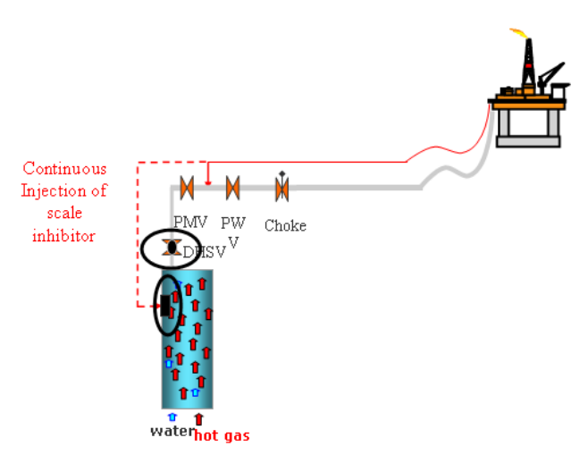
Figure 1. Overview of the subsea and downhole chemical injection systems in atypical field. Sketch of chemical injection up stream DHSV and the related expected challenges. DHS V=downhole safety valve, PWV=process wing valve and PM V=process master valve.
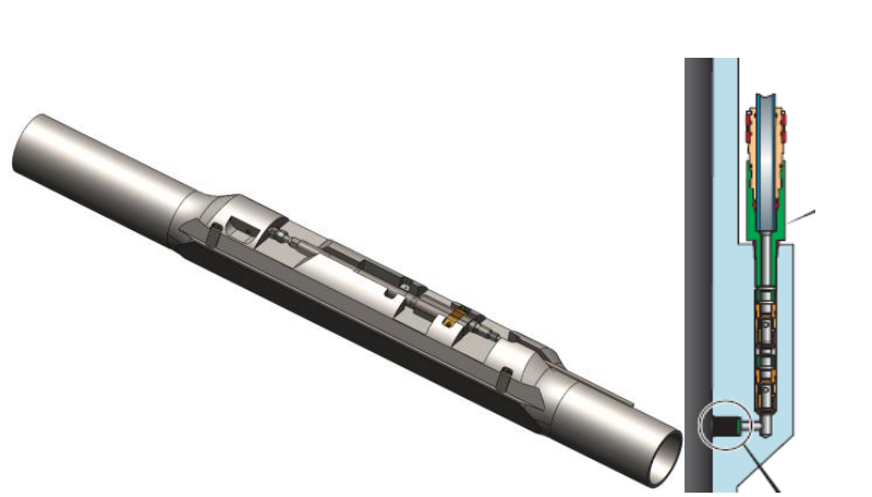
Figure 2. Sketch of atypical downhole chemical injection system with the mandrel and valve. The system is hooked up to the surface manifold, fed through-and connected to the tubing hanger on the annular side of the tubing. The chemical injection mandrel is traditionally placed deep in the well with intention to give chemical protection.
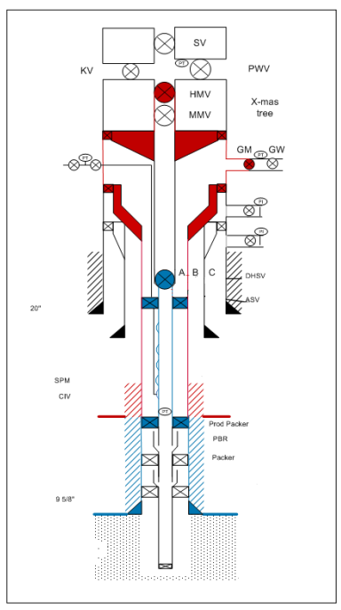
Figure 3. Typical well barrier schematic, where the blue colour represents the primary well barrier envelope; in this case the production tubing. The red colour represents the secondary barrier envelope; the casing. On the lefthand side is indicated the chemical injection, blackline with injection point to the production tubing in the area marked red(secondary barrier).
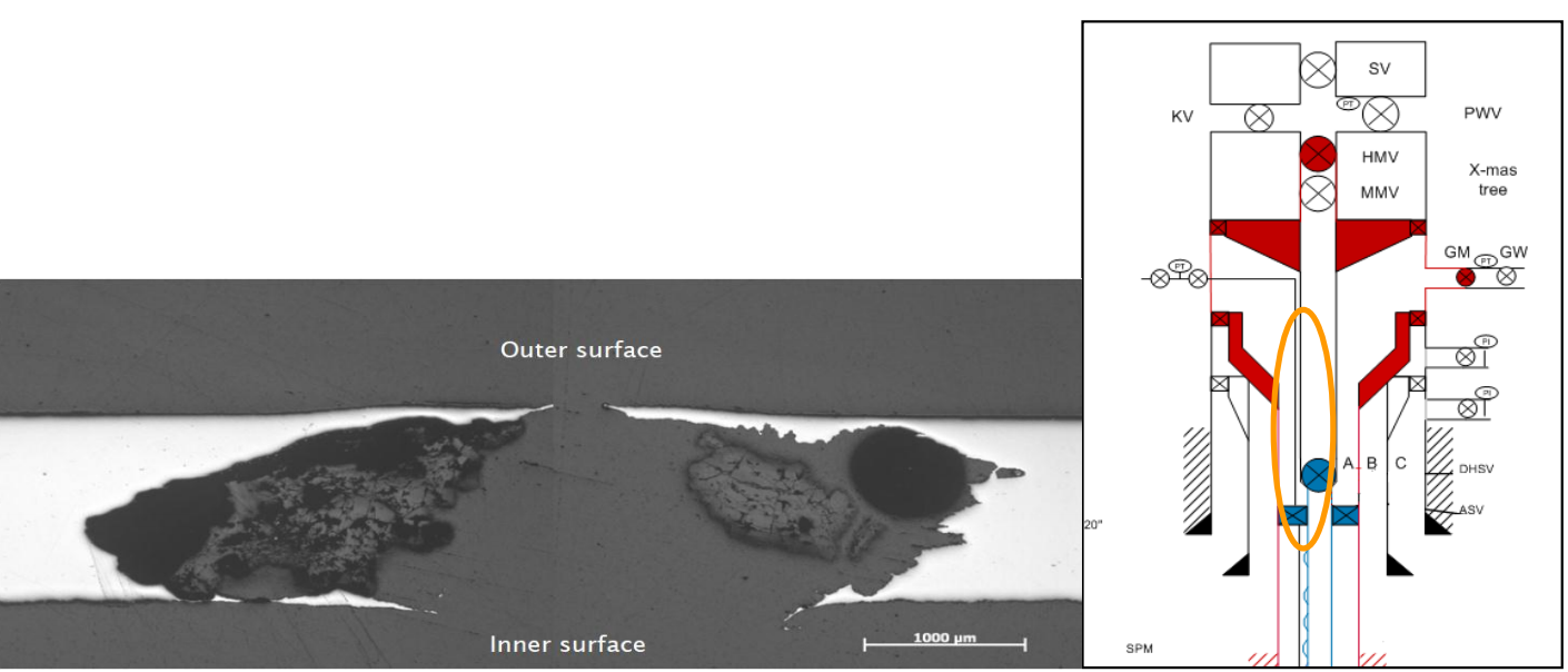
Figure 4. Pitted hole found in the upper section of the 3/8” injection line. The area is showed in the sketch of atypical well barrier schematic, marked with orange ellipse.
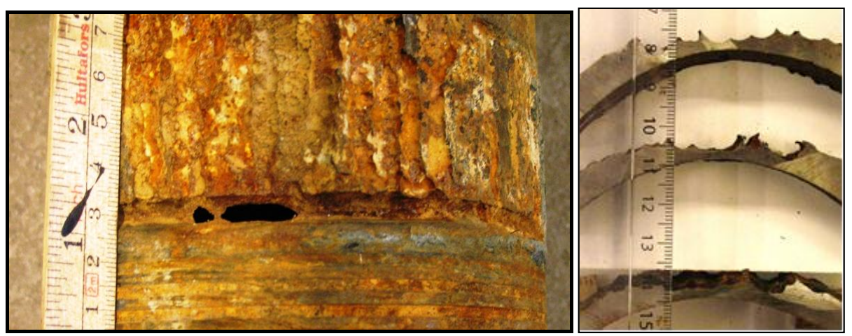
Figure 5. Severe corrosion attack on the 7” 3% Chrome tubing. The figure shows the corrosion attack after scale inhibitor sprayed from the pitted chemical injection line on to the production tubing.
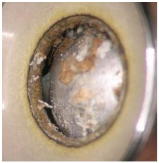
Figure 6. Debris found in the chemical injection valve. The debris in this case was metal shavings probably from the installation process in addition to some whitish debris. Examination of the white debris proved to be polymers with similar chemistry as the chemical injected
Post time: Apr-27-2022