Oil Production in Oilfields
How does control lines works in wells?
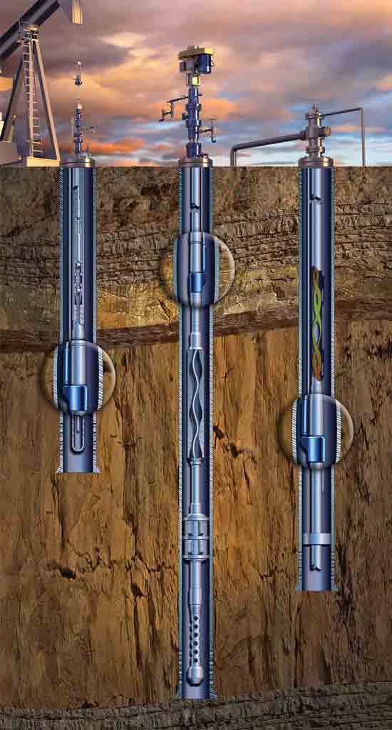
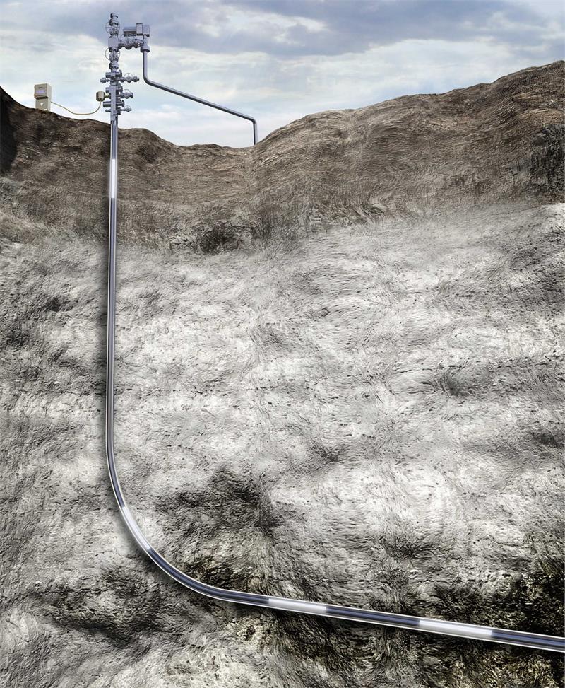
Control lines enable the transmission of signals, allow downhole data acquisition, and permit control and activation of downhole instruments.
The command and control signals can be sent from a location on the surface to the downhole tool in the wellbore. Data from downhole sensors can be sent to the surface systems for evaluation or use in certain well operations.
Downhole safety valves (DHSVs) are surface controlled sub-surface safety valves (SCSSV) hydraulically operated from a control panel on the surface. When hydraulic pressure is applied down a control line, the pressure forces a sleeve within the valve to slide down, opening the valve. On releasing the hydraulic pressure, the valve closes.
Meilong Tube's downhole hydraulic lines are used primarily as communication conduits for hydraulically operated downhole devices in oil, gas, and water-injection wells, where durability and resistance to extreme conditions are required. These lines can be custom configured for a variety of applications and downhole components.
All encapsulated materials are hydrolytically stable and are compatible with all typical well completion fluids, including high-pressure gas. The material selection is based on various criteria, including bottomhole temperature, hardness, tensile and tear strength, water absorption and gas permeability, oxidation, and abrasion and chemical resistance.
Control lines have undergone extensive development, including crush testing and high-pressure autoclave well simulation. Laboratory crush tests have demonstrated the increased loading under which encapsulated tubing can maintain functional integrity, particularly where wire-strand “bumper wires” are used.
Where are control lines used?
★ Intelligent wells requiring the functionality and reservoir management benefits of remote flow-control devices because of the costs or risks of interventions or an inability to support the surface infrastructure required in a remote location.
★ Land, platform, or subsea environments.
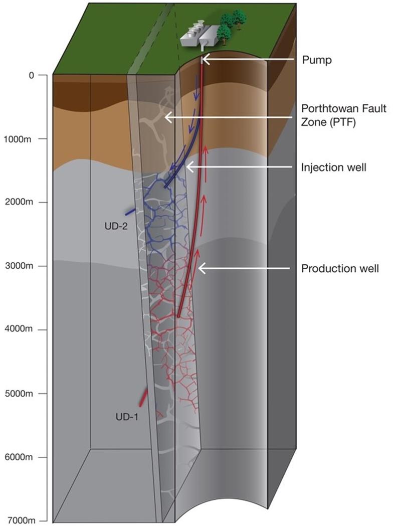
Geothermal Power Generation
Plant Types
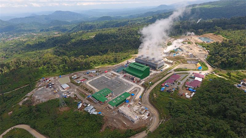
There are basically three types of geothermal plants used to generate electricity. The type of plant is determined primarily by the nature of the geothermal resource at the site.
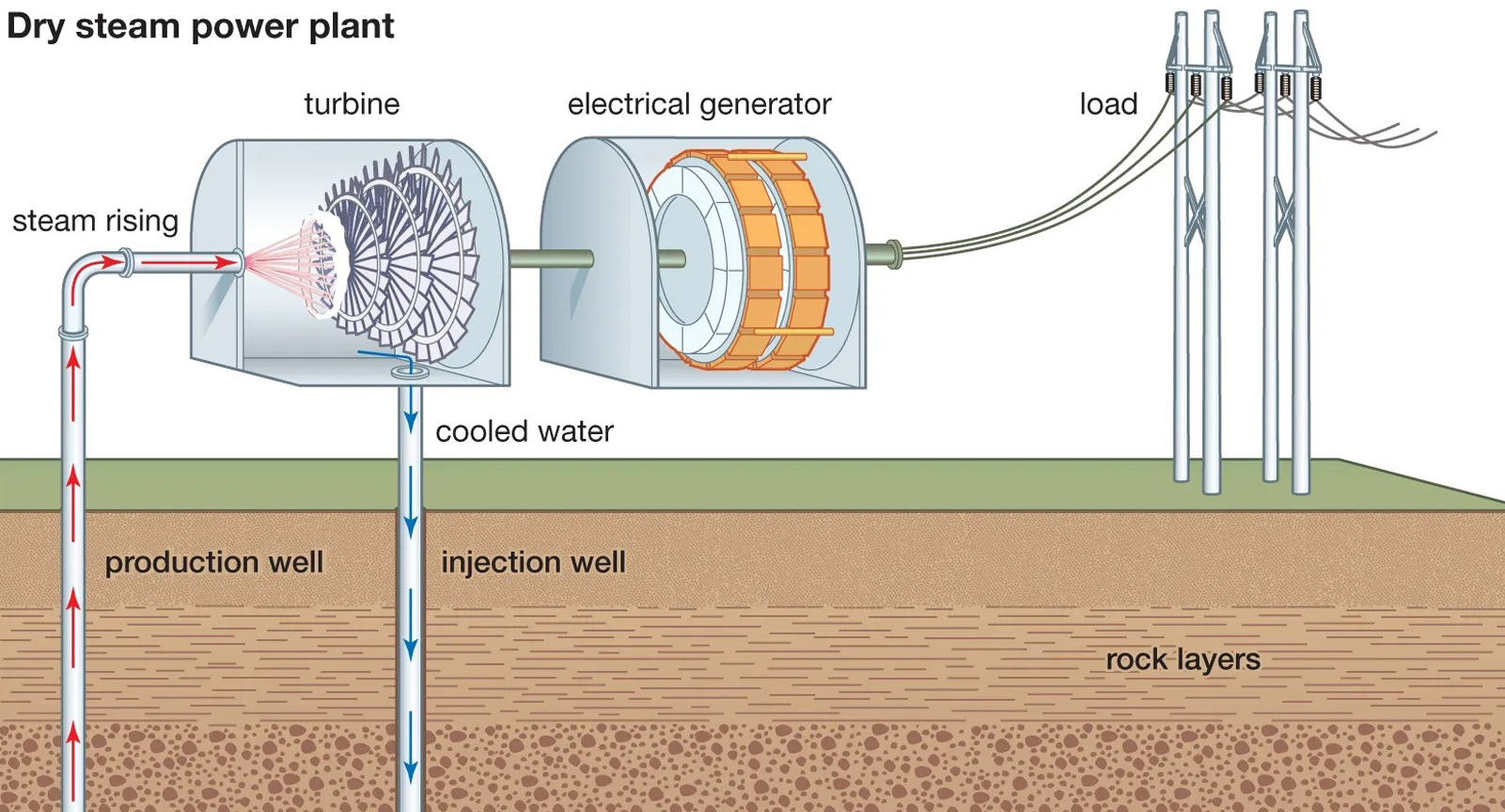
The so-called direct steam geothermal plant is applied when the geothermal resource produces steam directly from the well. The steam, after passing through separators (which remove small sand and rock particles) is fed to the turbine. These were the earliest types of plants developed in Italy and in the U.S. Unfortunately, steam resources are the rarest of the all geothermal resources and exist in only a few places in the world. Obviously steam plants would not be applied to low-temperature resources.
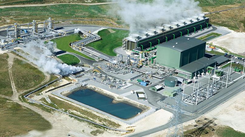
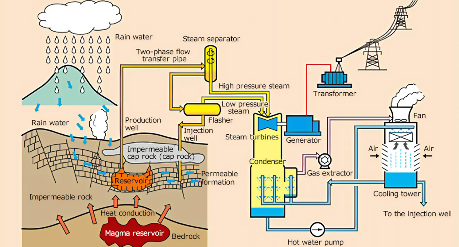
Flash steam plants are employed in cases where the geothermal resource produces high-temperature hot water or a combination of steam and hot water. The fluid from the well is delivered to a flash tank where a portion of the water flashes to steam and is directed to the turbine. The remaining water is directed to disposal (usually injection). Depending on the temperature of the resource it may be possible to use two stages of flash tanks. In this case, the water separated at the first stage tank is directed to a second stage flash tank where more (but lower pressure)steam is separated. Remaining water from the second stage tank is then directed to disposal. The so-called double flash plant delivers steam at two different pressures to the turbine. Again, this type of plant cannot be applied to low-temperature resources.
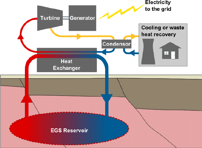
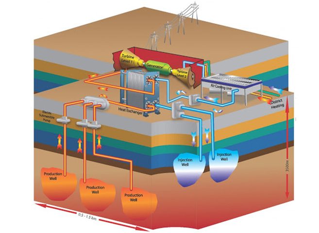
The third type of geothermal power plant is called the binary plant. The name derives from the fact that a second fluid in a closed cycle is used to operate the turbine rather than geothermal steam. Figure 1 presents a simplified diagram of a binary type geothermal plant. Geothermal fluid is passed through a heat exchanger called a boiler or vaporizer (in some plants, two heat exchangers in series the first a preheater and the second a vaporizer) where the heat in the geothermal fluid is transferred to the working fluid causing it to boil. Past working fluids in low temperature binary plants were CFC (Freon type) refrigerants. Current machines use hydrocarbons (isobutane, pentane etc) of HFC type refrigerants with the specific fluid chosen to match the geothermal resource temperature.
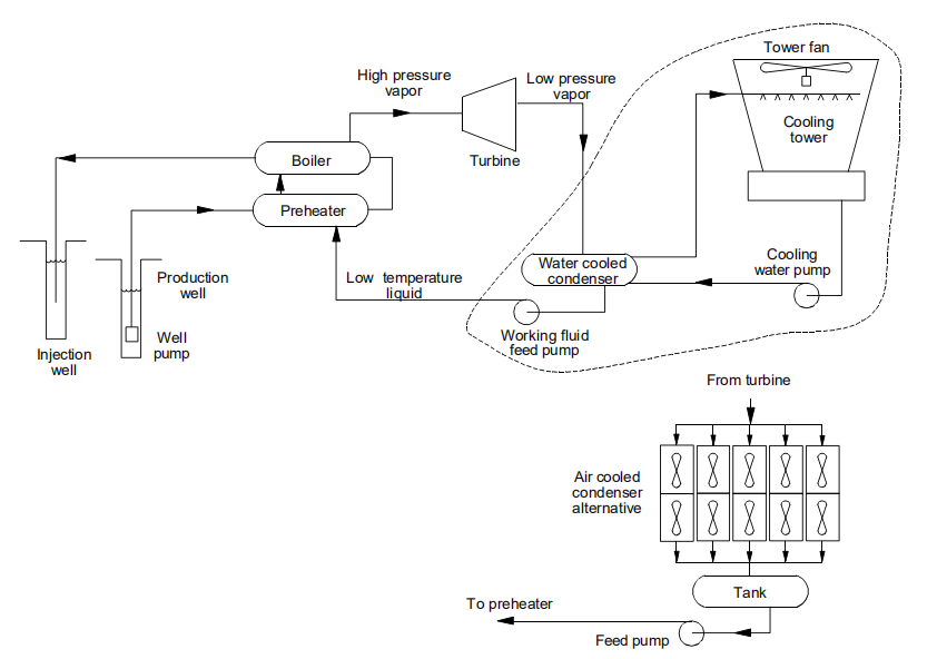
Figure 1. Binary geothermal power plant
The working fluid vapor is passed to the turbine where its energy content is converted to mechanical energy and delivered, through the shaft to the generator. The vapor exits the turbine to the condenser where it is converted back to a liquid. In most plants, cooling water is circulated between the condenser and a cooling tower to reject this heat to the atmosphere. An alternative is to use so called “dry coolers” or air cooled condensers which reject heat directly to the air without the need for cooling water. This design essentially eliminates any consumptive use of water by the plant for cooling. Dry cooling, because it operates at higher temperatures (especially in the key summer season) than cooling towers does result in lower plant efficiency. Liquid working fluid from the condenser is pumped back to the higher pressure preheater/vaporizer by the feed pump to repeat the cycle.
The binary cycle is the type of plant which would be used for low temperature geothermal applications. Currently, off-the-shelf binary equipment is available in modules of 200 to 1,000 kW.
POWER PLANT FUNDAMENTALS
Power Plant Components
The process of generating electricity from a low temperature geothermal heat source (or from steam in a conventional power plant) involves a process engineers refer to as a Rankine Cycle. In a conventional power plant, the cycle, as illustrated in figure 1, includes a boiler, turbine, generator, condenser, feed water pump, cooling tower and cooling water pump. Steam is generated in the boiler by burning a fuel (coal, oil, gas or uranium). The steam is passed to the turbine where, in expanding against the turbine blades, the heat energy in the steam is converted to mechanical energy causing rotation of the turbine. This mechanical motion is transferred, through a shaft to the generator where it is converted to electrical energy. After passing through the turbine the steam is converted back to liquid water in the condenser of the power plant. Through the process of condensation, heat not used by the turbine is released to the cooling water. The cooling water, is delivered to the cooling tower where the “waste heat” from the cycle is rejected to the atmosphere. Steam condensate is delivered to the boiler by the feed pump to repeat the process.
In summary, a power plant is simply a cycle that facilitates the conversion of energy from one form to another. In this case the chemical energy in the fuel is converted to heat (at the boiler), and then to mechanical energy (in the turbine) and finally to electrical energy (in the generator). Although the energy content of the final product, electricity, is normally expressed in units of watts-hours or kilowatt-hours (1000 watt-hours or 1kW-hr), calculations of plant performance are often done in units of BTU’s. It is convenient to remember that 1 kilowatt-hour is the energy equivalent of 3413 BTU. One of the most important determinations about a power plant is how much energy input (fuel) is required to produce a given electrical output.
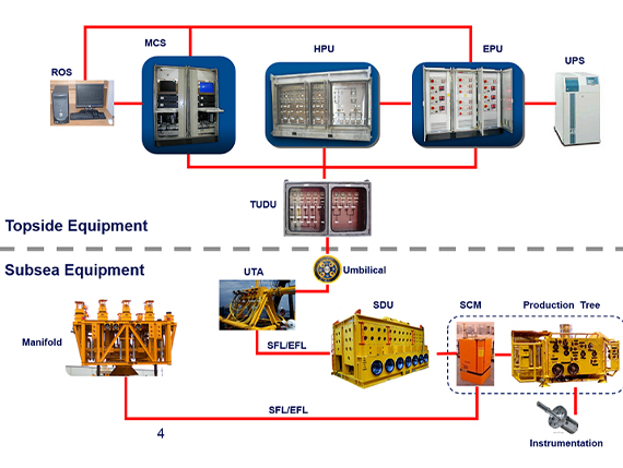
Subsea Umbilicals
Main Functions
Provide hydraulic power to subsea control systems, such as to open/close valves
Provide electric power and control signals to subsea control systems
Deliver production chemicals for subsea injection at tree or downhole
Deliver gas for gas lift operation
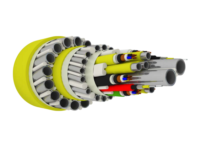
To delivery these function, a deep water umbilical can include
Chemical injection tubes
Hydraulic supply tubes
Electrical control signal cables
Electrical Power cables
Fiber optic signal
Large tubes for gas lift
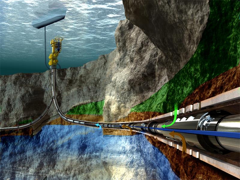
A subsea umbilical is an assembly of hydraulic hoses which can also include electrical cables or optic fibres, used to control subsea structures from an offshore platform or a floating vessel. It is an essential part of subsea production system, without which sustained economical subsea petroleum production is not possible.
Key Components
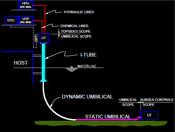
Topside Umbilical Termination Assembly (TUTA)
The Topside Umbilical Termination Assembly (TUTA) provides the interface between the main umbilical and the topside control equipment. The unit is a free standing enclosure that can be bolted or welded in a location adjacent to the umbilical hang-off in a hazardous exposed environment onboard the topside facility. These units are usually tailor-made to customer requirements with a view to hydraulic, pneumatic, power, signal, fiber optic, and material selection.
The TUTA usually incorporates electrical junction boxes for the electrical power and communication cables, as well as tube work, gauges, and block and bleed valves for the appropriate hydraulic and chemical supplies.
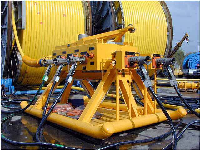
(Subsea) Umbilical Termination Assembly (UTA)
UTA, sitting on top of a mud pad, is a multi-plexed electro-hydraulic system allows many subsea control modules to be connected to the same communications, electrical and hydraulic supply lines. The result is that many wells can be controlled via one umbilical. From the UTA, the connections to the individual wells and SCMs are made with jumper assemblies.
Steel Flying Leads (SFL)
Flying leads provide electrical/hydraulic/chemical connections from the UTA to individual trees/control pods. They are part of the subsea distribution system that distributes umbilical functionalities to their intended service targets. They are typically installed after umbilical and connected by ROV.
Umbilical Materials
Depending on the types of application, the following materials are typically available:
Thermoplastic
Pros: It is cheap, fast delivery, and fatigue resistant
Cons: Not suitable for deep water; chemical compatibility problem; aging, etc.
Zinc coated Nitronic 19D duplex stainless steel
Pros:
Lower cost compared with super duplex stainless steel (SDSS)
Higher yield strength compared to 316L
Internal corrosion resistance
Compatible for hydraulic and most chemical injection service
Qualified for dynamic service
Cons:
External corrosion protection required – extruded zinc
Concerns about the reliability of seam welds in some sizes
Tubes are heavier and larger than equivalent SDSS – hang off and installation concerns
Stainless Steel 316L
Pros:
Low cost
Needs little or no cathodic protection for short duration
Low yield strength
Competitive with thermoplastic for low pressure, shallow water tiebacks –cheaper for short field life
Cons:
Not qualified for dynamic service
chloride pitting susceptible
Super Duplex Stainless Steel (Pitting Resistance Equivalent - PRE >40)
Pros:
High strength means small diameter, light weight for installation and hang off.
High resistance to stress corrosion cracking in chloride environments (pitting resistance equivalent > 40) means no coating or CP required.
Extrusion process means no difficult-to-inspect seam welds.
Cons:
Inter-metallic phase (sigma) formation during manufacture and welding must be controlled.
Highest cost, longest lead times of steels used for umbilical tubes
Zinc coated carbon steel (ZCCS)
Pros:
Low cost relative to SDSS
Qualified for dynamic service
Cons:
Seam welded
Less Internal corrosion resistance than 19D
Heavy and large diameter compared to SDSS
Umbilical commissioning
Newly installed umbilicals typically have storage fluids in them. The storage fluids need to be displaced out by the intended products before they are utilized for production. Cares must be taken to look out for potential incompatibility problems that can result in precipitates and cause umbilical tubes to get plugged up. A proper buffer fluid is required if incompatibility is expected. For example, to commission an asphaltene inhibitor line, a mutual solvent like EGMBE is needed to provide buffer between the asphaltene inhibitor and storage fluid since they are typically incompatible.